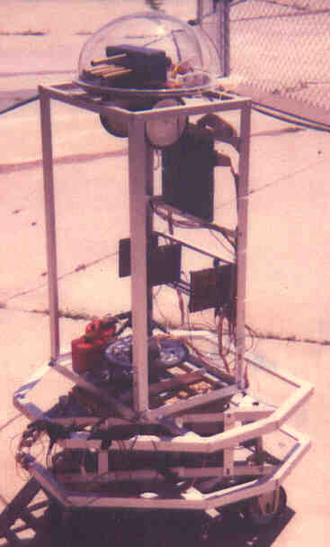
 S.A.M. (Short
for "Sentient, Autonomous Mechanism" or "Smart Ass Machine", depending
on his (and my) mood on a given day) was one of my first real robot projects, started in
1978 when I was around 15. His "brain" was a single-board Z-80 computer
(the big square object in the middle of his "back" in this picture), with many
bits of TTL I/O, a couple of serial ports, a bunch of counter-timers, and several D/A
& A/D channels. The base was taken from the book "How to Build a Computer
Controlled Robot" by Todd Loofbourrow - I had built the robot in the book, and had
used my KIM-1 to control it. Later, I decided that just a little platform was kind
of boring, so I added the upper torso shown here. The torso (mounted on a
"lazy-susan" turntable bearing) is rotated by a heavy-duty gear motor driving a
chain and sprocket assembly from a bicycle. The base is powered by two of the
(apparently no longer available, which is sad) all-metal rubber-tired "motorized
wheel" assemblies that Herbach & Rademan used to sell, with a large rubber-tired
caster in front. The head platform (mounted on a small "lazy-susan"
bearing) was originally rotated by a surplus gearbox from a Mattel "Big Trak"
with some rubber-tired wheels mounted on the output shafts. This arrangement was
later replaced by a small gear-head motor driving a large gear mounted to the center of
the turntable. The device in the head with the tubes sticking out the front is a
directional light tracking device. Each tube has a CDS photocell at the bottom, and
is painted flat black inside. A comparator circuit tells the computer which
direction the brightest light is coming from. This device could also tilt up and
down with a small gear-head motor, to track light sources vertically. Most of the
circuitry was installed on small plug-boards from Radio Shack, mounted in a card rack
below the CPU card. This rack could be tipped back 90 degrees to facilitate easier
access for testing. In addition to motor driver circuits, there was a "Sweet
Talker" speech synthesizer board so he could talk. Power came from a large
"gel-cell" marine battery (for powering trolling motors on boats), which was
slung near the ground in the center of the base. Two 6V lantern batteries (later
replaced by a 12V motorcycle battery) provided separate power for the electronics.
All motors were isolated from the electronics via relays and/or opto-isolators.
After these pictures were taken, a set of metal panels was installed on the
"facets" of the base, with lever switches behind them for collision sensing.
A Polaroid sonar range-finder was also added later. If you check out the
other photos of S.A.M., you will notice an "arm" sticking out the front.
This was a prototype made from an old swing-arm desk lamp and some
"fingers" from a robot hand design using brass tubing, bicycle chain, and
1/16" steel cable to allow natural bending of each finger. It was later
replaced with a much heavier duty aluminum framework arm operated by two 12VDC
"linear actuators".
S.A.M. (Short
for "Sentient, Autonomous Mechanism" or "Smart Ass Machine", depending
on his (and my) mood on a given day) was one of my first real robot projects, started in
1978 when I was around 15. His "brain" was a single-board Z-80 computer
(the big square object in the middle of his "back" in this picture), with many
bits of TTL I/O, a couple of serial ports, a bunch of counter-timers, and several D/A
& A/D channels. The base was taken from the book "How to Build a Computer
Controlled Robot" by Todd Loofbourrow - I had built the robot in the book, and had
used my KIM-1 to control it. Later, I decided that just a little platform was kind
of boring, so I added the upper torso shown here. The torso (mounted on a
"lazy-susan" turntable bearing) is rotated by a heavy-duty gear motor driving a
chain and sprocket assembly from a bicycle. The base is powered by two of the
(apparently no longer available, which is sad) all-metal rubber-tired "motorized
wheel" assemblies that Herbach & Rademan used to sell, with a large rubber-tired
caster in front. The head platform (mounted on a small "lazy-susan"
bearing) was originally rotated by a surplus gearbox from a Mattel "Big Trak"
with some rubber-tired wheels mounted on the output shafts. This arrangement was
later replaced by a small gear-head motor driving a large gear mounted to the center of
the turntable. The device in the head with the tubes sticking out the front is a
directional light tracking device. Each tube has a CDS photocell at the bottom, and
is painted flat black inside. A comparator circuit tells the computer which
direction the brightest light is coming from. This device could also tilt up and
down with a small gear-head motor, to track light sources vertically. Most of the
circuitry was installed on small plug-boards from Radio Shack, mounted in a card rack
below the CPU card. This rack could be tipped back 90 degrees to facilitate easier
access for testing. In addition to motor driver circuits, there was a "Sweet
Talker" speech synthesizer board so he could talk. Power came from a large
"gel-cell" marine battery (for powering trolling motors on boats), which was
slung near the ground in the center of the base. Two 6V lantern batteries (later
replaced by a 12V motorcycle battery) provided separate power for the electronics.
All motors were isolated from the electronics via relays and/or opto-isolators.
After these pictures were taken, a set of metal panels was installed on the
"facets" of the base, with lever switches behind them for collision sensing.
A Polaroid sonar range-finder was also added later. If you check out the
other photos of S.A.M., you will notice an "arm" sticking out the front.
This was a prototype made from an old swing-arm desk lamp and some
"fingers" from a robot hand design using brass tubing, bicycle chain, and
1/16" steel cable to allow natural bending of each finger. It was later
replaced with a much heavier duty aluminum framework arm operated by two 12VDC
"linear actuators".