| Bill's Home-Built Gingery Metal Lathe |
(You can click on a photo to see a larger version.) |
 |
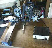
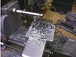
Here you can see the finished, assembled castings for the carriage, the cross-slide, and the pivoting base for the compound cross-slide, along with their various clamps and gib screws. Also visible is the ball-crank which moves the cross-slide. I used an 8" carriage bolt for the threaded rod, and found that the fit of the ball-crank was a little sloppy for my liking, as I discovered that although the plan calls for a 1/4" hole in the crank, the non-threaded part of the carriage bolt is actually a bit smaller. |
I was able to find a piece of brass tubing which fits perfectly between the shaft and the crank, keeping it snug and perfectly centered when the set screw is tightened. |
 |
 |
I also found that the shaft had a tendency to wobble and bind a bit when turned, so I added a second collar with set screw between the crank and the cross-slide casting, and cut the brass tubing to extend all the way through the crank, both collars, and the casting. This makes for a nice snug fit when it's assembled, while reducing friction and allowing smooth movement when the crank is turned. |
| Update 8/1/99: | |
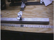
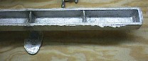
| Today, I took the plunge and poured the lathe bed casting. Although this is the first casting in the book, it requires a specially made flask, and is large and intimidating, so I put it off until I was more confident in my casting skills. I'm glad I did; the flask was quite heavy (I'd guess around 100lbs) when packed full of oil-bonded sand, and required assistance to roll over. Also, it involved one of the largest quantities of aluminum I've melted thus far. Overall, I'm very pleased with the way the casting turned out. Here are some photos of the rough casting, right out of the sand. |
|
| Here's a bottom view. There's a bit of discoloration in the
center support rib, since the sprue was right above it and I think things got a little
warm...
|
 |
|
|
|
| "Sir, we're picking up something strange on radar. It appears
to be a submarine of an unknown design..." (Does this look like the
"SeaView" to you, too?) |
 |
 |
|
| Update 9/18/99: | |
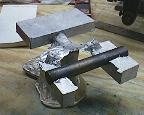
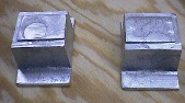
The apron and headstock
caps as they came out of the sand. I had the patterns ready at the same time, so I
cast them together off a common sprue. It was near sunset when I started, so I ended
up pouring by the light of the glowing aluminum (no electricity in the barn... yet...).
It was pretty interesting, actually. I got to see all these
little flames dancing over the surface of the oil-bonded sand for several minutes after I
poured; I assume it's some of the oil burning off... |
|
|
|
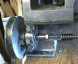
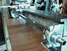
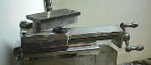
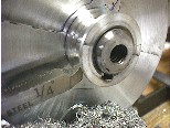
Here's a closeup of the
left end of the lead screw with bearing journal, bearing, and pulley. Careful
observers will note that the bearing is, in fact, a modified commercially cast
"pillow block" with brass bushing. After 3 attempts to cast the
Gingery-model bearings ended in failure due first to pattern problems and then to gas
pockets in the castings, I did what any red-blooded American would do; I gave up and threw
money at the problem. ;-) I bought a couple of pillow blocks with the correct
bushing diameter, sawed off the mounting bolt |
|
|
|
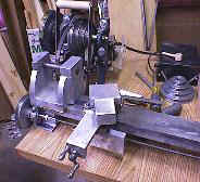
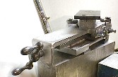
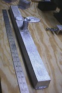
This view of the lathe that
makes it look like it's the size of an aircraft carrier. You wouldn't guess that
it's only 2 feet long! Next up, I have to cast the leadscrew crank (I'm thinking
brass just for looks...) and the split nut and split nut lever, and build the boring bar
support assembly to bore out the headstock! |
|
|
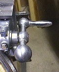
This was a pain in the butt. For some reason, I had a terrible time with this casting. Part of the problem was that I didn't have the dowel in the pattern extending above the top of the center ball, so it was hard to get the steel core positioned correctly in the mold. I ended up having to melt the core out of messed-up castings on two occasions. After I added a dowel at the top of the pattern to leave a better alignment print for the core, I poured a brass crank because I thought it would be pretty, but it ended up with a shrink cavity that ruined the ball at the crank end. <*sigh> It being my 4th attempt and all, I abandoned brass, at least for the moment, because I thought it caused the cavity. After two more attempts with zinc, still with shrinkage cavities, I finally added a riser to the mold, right next to the ball end, and that did the trick. <*whew> |
| Update 10/17/99: | |
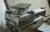
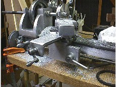
| Progress is Made! Here
you can see several new pieces, including the cross feed (minus the crank and feed screw;
I'll get to that soon. For now, I've just got the gib screws cranked down tight...)
the half-nut engage lever, and the tool post. Not visible are the half-nut (I'll try
to get some pictures next time I have the thing apart) and the spring-loaded pawl which
holds the half-nut in the engaged or disengaged position.) |
 |
 |
|
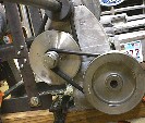
| The finished reduction pulley left/center
attached to the headstock with an axle bolt and appropriate spacers. The round
rubber vacuum cleaner belts which drive the carriage are installed in this picture. |
|
|