Popular Electronics
AUGUST 1976
[33] [34] [35] [36] [37] [38]
[Part 1] [Part 2] [Part 3] [Part 4]


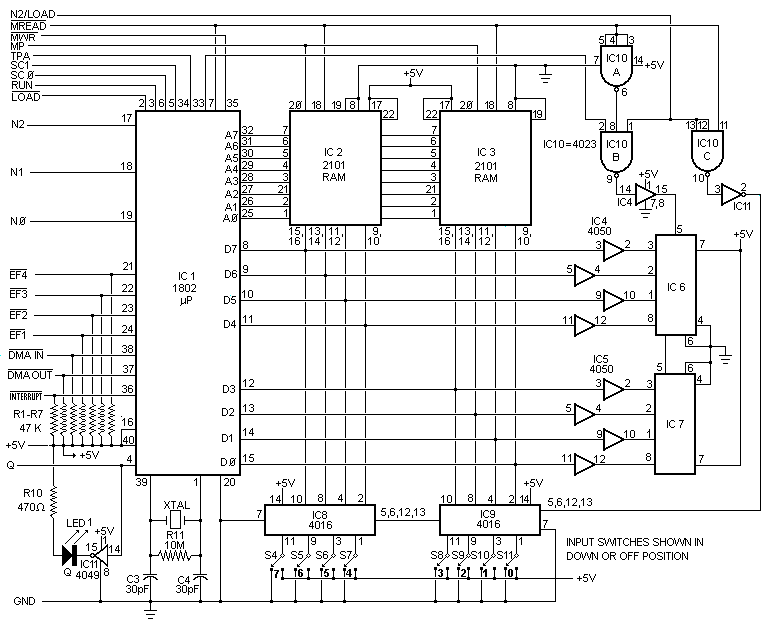
Fig. 4. Complete circuit for the Elf computer. Identified connections on the left go to the "front panel" with the eight data switches. The remaining can be left "floating" at 1802, or tied to terminal strip.

PARTS LIST
  • C1, C2--10-µF, 16-volt electrolytic capacitor
  • C3, C4--30-pF disc capacitor
  • D1 through D6--IN914 switching diode
  • IC1--CDP1802 COSMAC microprocessor chip (RCA)
  • IC2, IC3--2101 (256 x 4) static RAM IC
  • IC4, IC5--4050 noninverting hex buffer IC
  • IC6, IC7--Hex LED display (H-P No. 5082-7340)
  • IC8, IC9--4016 quad bilateral switch IC
  • IC10--4023 triple 3-input NAND gate IC
  • IC11--4049 inverting hex buffer IC
  • IC12--4013 dual D flip-flop IC
  • IC13--LM309K 5-volt regulator IC
  • LED1--Red light-emitting diode
  • R1 through R9--47,000-ohm, ¼-watt resistor
  • R10--470-ohm, ¼-watt resistor
  • R11--10-megohm, ¼-watt resistor
  • S1 through S11--Spdt toggle switch
  • S12--Pushbutton switch with one set each normally open and normally closed contacts
  • XTAL--1-to-2-MHz crystal (see text)
  • Misc.--5½" x 4" (14 x 10.1cm) perforated board with 0.1" (2.54 cm) hole spacing;
  • 5½" x 2" (14 x 5.1cm) piece of thin aluminum; ¾" x 3/8" (19.1 x 9.5 cm) pine for chassis rails; 14-pin IC sockets (4); 16-pin IC sockets (3); 22-pin IC sockets (2); 40-pin IC socket; connector for power supply; 9-volt, 350-mA dc power source; 1¼" x ¾" x 1/8" (31.8 x 19.1 x 3.2 mm) piece of aluminum; dry-transfer lettering kit; machine and wood hardware; hookup wire; solder; etc.
    Note: the CDP1802 COSMAC microprocessor chip is available from any RCA parts distributor as is the COSMAC user manual.

    automatically incremented so that it points to the next instruction to be fetched. Branch instructions can be used to change the address in the program counter to permit jumping (branching) to a different part of the program when desired. The digit in the 4-bit P register specifies which 16-bit general-purpose register is being used as the program counter.

    Timing Sequence. Since many of the 1802 microprocessor's instructions are only one-byte long and require two machine cycles, the first cycle is always an instruction fetch, or memory read. The fetched instruction is executed during the next machine cycle, which could be a memory-read memory-write, or register-transfer type of cycle.

    Program execution always consists of a sequence of fetch-execute cycles, and the two SC0 and SC1 lines (see Fig. 4 and Fig. 5) indicate what type of cycle is being performed according to the following criteria:
    SC1SC0Type of Machine Cycle
    00instruction fetch
    01instruction execute
    10DMA in/out
    11interrupt
    Direct memory access (DMA) and interrupt are special types of cycles, which we will discuss later.

    Circuit timing is shown in Fig. 6.

    [33] [34] [35] [36] [37] [38]
    [Part 1] [Part 2] [Part 3] [Part 4]
    35 AUGUST 1976