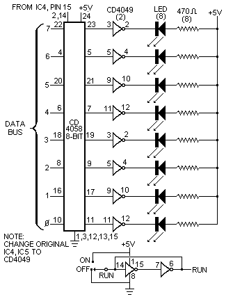
Fig. 1 Circuit for a discrete LED display.

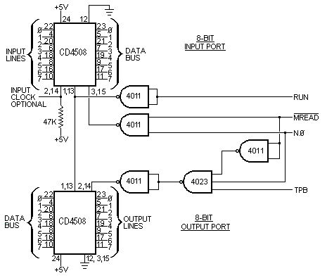
these output lines to drive suitable transistors to control relays, lamps or LED's, or battery-powered motors, you can have the computer sequence lights, control animated displays or robots, or control a slide projector in response to tones from an audio tape. You can use the existing Q line output in the same manner for a single operation.

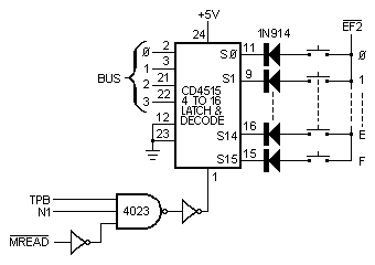
A simple method of controlling up to 16 output lines or monitoring the states of 16 switches is shown in Fig. 3. A 62 instruction will set the low-order digit of a memory byte into the 4-bit CD4515 register. The output line corresponding to this digit will go low, while the other 15 remain high. To make things more interesting, the computer can determine whether the switch attached to the selected output line is closed or not by testing EF2 with a branch instruction.

The following program continuously examines all 16 switches in sequence and stops with the number of any closed switch from 0 to F in the low-order digit of R3.0:
Step   M     Bytes   Comment
  1  0000  F8 FF A2  FF-->R2.0 (memory pointer)
  2  0003  13 52 E2  R3 + 1, R3.0-->MX, 2-->X
  3  0006     62 22  MX-->CD4515 (select switch)
  4  0008     3D 03  Repeat step 2 if switch is open
  5  000A     30 0A  Stop with R3.0 = closed switch number
The diodes can be omitted if only one switch at a time will be closed. This circuit and an appropriate program could permit data and instruction bytes to be loaded into memory a digit at a time from a hex keyboard instead of toggle switches. Switch debouncing could be performed with a programmed delay following each key depression. A 64-character keyboard could be used by treating it as four groups of 16 keys each, with the common side of each key group connected to a different flag line. In fact, a program to generate the Morse code equivalent of each key could be written using the Q line as the output.
This circuit can also be used to select one of 16 external devices or I/O ports if desired. Using the latter technique would permit up to 128 I/O lines. Cascading CD4515's would permit even larger numbers of I/O lines to be handled.
A low-cost video terminal can be made using the "Scopewriter" (POPULAR ELECTRONICS, August 1974), or you can interface your computer with a cassette data interchange system.
We have only scratched the surface of I/O circuits for the Elf. The real fun (and program training) starts when you think of new things to attach to the output lines and start writing programs to activate them.
The major drawback with a RAM, or memory, system is that data stored in it is erased when the main power source is shut down. (Of course, if you could use a ROM, this wouldn't be a problem. However, ROM's must be preprogrammed with the memory data you wish to save, a costly and time-consuming approach.) Adding a cassette interface doesn't entirely eliminate the problem because a "bootstrap" is still required to be stored in memory to run the cassette.
The use of low-power COSMOS RAM IC's and a 9-volt mercury battery, as shown in Fig. 4, will allow you to save programs in memory for up to six months even with the main power to the computer turned off. The 1822 RAM's shown are in-compatible with the 2101's specified for the original project, but some of the RAM's must be rewired as shown.
With the COSMOS RAM's installed, you can turn off power to the computer at any time. The mercury battery will supply the required standby power to the memory system so that the program will be ready to run immediately when the computer is again powered up. The newly added STANDBY switch should be turned on (+5 volts) only after power is turned on. It should be off to hold pin 17 of the RAM's at ground potential before removing power from the system.