using software, display them successively onscreen to produce animation effects. Low-resolution alphanumerics can also be created.
Since the basic Elf has only 256 bytes of memory, we will show how to display the entire memory on the screen. The memory is mapped as shown in Fig. 1, in an array of 64 spots wide (eight bytes with eight bits/byte) by 32 spots high to make a total of 256 bytes.
The byte at M(0000) is displayed at tthe upper-left of the screen; each row on the screen is equivalent to eight memory bytes. Byte M(00FF) appears at the bottom-right of the screen.
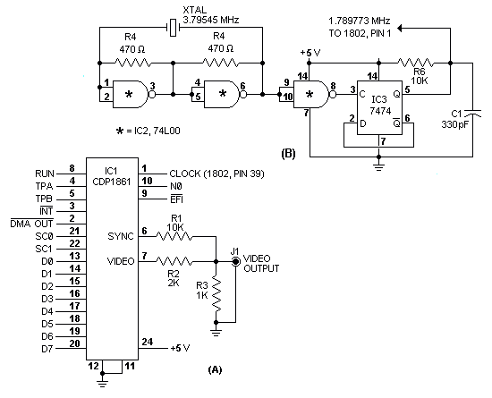
Circuit Operation. The entire schematic diagram for the Pixie graphics display system is shown in Fig. 2A. It consists of five components: the 1861 chip, a phono jack for the video output, and three resistors. The circuit shown in Fig. 2B may be used to replace the original crystal used in the Elf microcomputer. This is necessary because, to use the graphics display, the original crystal frequency must be changed to approximately 1.760640 MHz to generate the correct TV horizontal and vertical sync pulses. Crystals of this frequency may be expensive. The Fig. 2B circuit uses a [44]

"PIXIE PARTS LIST"
C1 -- 330-pF disc capacitor
IC1 -- CDP 1861 video IC (RCA)
IC2 -- 74L00 low-power quad 2-input NAND gate IC
IC3 -- 7474 dual-D flip-flop IC
J1 -- Phono jack
All resistors 1/4-watt, 10% tolerance:
R1,R6 -- 10,000 ohms
R2 -- 2000 ohms
R3 -- 1000 ohms
R4,R5 -- 470 ohms
XTAL -- 3.58-MHz crystal
Misc. -- Printed circuit or perforated board;
         IC sockets (one 24-pin, two 14-pin);
         spacers; machine hardware;
         hookup wire solder; etc.
Note: The following are available from Netronics,
      333 Litchfield Rd., New Milford, CN 06776:
      kit including all of above components except
      those under "Misc." at $24.95;
      complete Elf II kit (basic Elf plus Pixie
      components and hexadecimal keyboard), including
      pc board, keyboard support IC's and expansion
      bus at $99.95, plus $3.00 shipping.
      Connecticut residents, add 7% sales tax.