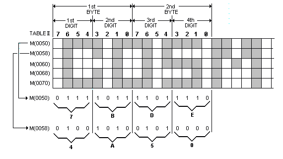
Fig. 3. Diagram showing how to create your own display. This one is for parts of five lines of Spaceship Program.

Fig. 3. Diagram showing how to create your own display. This one is
for parts of five lines of Spaceship Program.
quire three cycles for each execution. These are used only to provide the delay required to between the beginning of the interrupt routine and the first eight-byte DMA request generated by the 1861 display circuits.
Each of the eight display refresh bytes requested by the 1861 is internally converted to a bit serial form and used to provide the luminance (brightness) pulses that come out of the 1861 at pin 7. The actual raster display consists of 262 horizontal lines for each frame, and there are 60 frames per second. Each display spot is four raster lines high, which means that each eight-byte display row must be repeated four times. With the interrupt routine, R0 is initially set to M(0000) to M(0007) to be fetched and displayed. The time of each raster line is exactly 14 machine cycles to permit the transfer of eight bytes (eight cycles) plus the execution of three two-cycle instructions during each raster line time. Following the eight DMA cycles required to refresh the first eight bytes, R0 is restored to its original value so that it remains pointing at the same eight bytes.
The E2 20 A0 instructions at M(0020), M(0023), and M(0026) are used to occupy six machine cycles between the DMA requests and to restore R0 to its initial value before incrementing it by eight during the eight-byte DMA request. The 20 instruction decrements R0.1 back to its initial value if a 256-byte page boundary was crossed during the preceding eight DMA cycles.
After the first group of eight bytes has been displayed for four raster line times, R0 is permitted to advance to the next group of eight bytes to be displayed. This process is continued until 32 groups of eight bytes each (256 total) have been displayed. At this time, the circuits in the 1861 chip cause line EF1=1 (at pin 9) and the interrupt routine terminates.
Other Considerations. The raster refresh involves the display of 32 groups of eight bytes, and each row of eight bytes is repeated on four raster line scans. This means that the display refresh ties up the 1802 µP for slightly more than 128 raster lines (32 x 4). Since there are 262 raster lines per frame, the µP spends about 50% of its time performing the display-refresh function.
Since the 1802 and the 1861 clocks must remain synchronized, none of the three-cycle instructions described in the 1802's user's manual should be used in programs that run concurrently with this display. The only exception is the use of the C4 instruction in the interrupt routine.
The sample program given in Table I was designed to run in expanded-memory systems as well as in the basic 256-byte Elf. In the expanded system, just change the bytes at M(0019) and M(001C) so that R0 initially points to any 256-byte segment of the memory you wish to display on the raster. You can write any other main program to run concurrently with this interrupt routine.
The 1861 chip can also be used to display any number of memory bytes from eight to 1024 by rewriting the interrupt routine. For example, change the byte at M(0024) from 20 to 80, and you will see 512 bytes displayed on the CRT screen as 64 spots horizontally by 64 spots vertically. If you have only 256 bytes of memory in your system, you will ass the same 256 bytes repeated twice on the screen. When displaying 512 bytes, each spot represents half the [46]